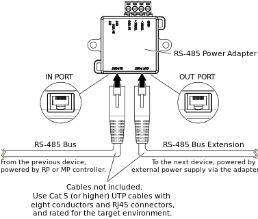
The RS-485 Power Adapter can be used for injecting 24 VDC from an external 24 VDC power supply to an RS-485 based network such as Room Bus or Sensor Bus. This is useful, for example, in applications where you want to extend the RS-485 bus by connecting (daisy-chaining) additional devices, which the RP or MP controller would otherwise not be able to power. The external power supply is connected to the bus via the adapter.
Important:
Before use, check the required ratings for the external 24 VDC power supply.
For more information, see RS-485 Power Adapter
.
Examples
This section gives an example of how the adapter can be used to inject 24 VDC to an RS-485 bus for extension of the bus when more devices than the allowed limit need to be connected:
Example with Sensor Bus for an MP-V controller
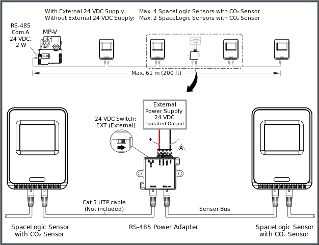
The following figure shows an example of how an RS-485 Power Adapter is used to inject 24 VDC from an external 24 VDC power supply to an MP-V controller Sensor Bus so that the maximum number of SpaceLogic Sensor devices with sensor bases with CO
2
option can be increased from two to four devices.
For more information, see MP-V Sensor Bus
.The adapter is typically placed after the second device on the bus where it is used to power the third and fourth devices. The adapter is connected to the Sensor Bus by means of two Cat 5 (or higher) UTP cables (not included). The isolated, non-grounded (floating) 24 VDC output from the external power supply is connected to the screw terminals marked 24 VDC and GND on the adapter.
action_zoom_plus_stroke

Figure:
Example with an RS-485 Power Adapter and an external 24 VDC power supply used to extend an MP-V controller Sensor Bus to four SpaceLogic Sensors with CO
action_zoom_plus_stroke

The negative terminal (–) on the external 24 VDC power supply should not be connected to local ground. The isolated (floating) 24 VDC output from the power supply should be connected to the GND (–) and 24 VDC (+) terminals on the adapter.
Connection of RJ45 Ports to RP or MP Controller RS-485 Com Port and RS-485 Bus
Separate connection cables are required to connect the two RJ45 ports on the RS-485 Power Adapter to the RS-485 Com port (RJ45) on the RP or MP controller and to other daisy-chained devices with RJ45 interface on the RS-485 bus. The cables are not included and need to be purchased separately.
Use a Cat 5 (or higher) unshielded, straight-through wired cable with eight conductors (four twisted pairs) and RJ45 connectors. Use a cable with the wire size (cross-sectional area) 22 to 26 AWG (0.34 to 0.14 mm²), and a rating that meets the requirements of the target environment. For example, when devices are installed in a space that handles conditioned air or return air, the cables typically need to be plenum-rated.
|
Notice
|
|
LOSS OF COMMUNICATION
Use a Cat 5 or higher unshielded twisted pair cable with eight conductors (four twisted pairs), a cross-sectional area of 22 to 26 AWG (0.34 to 0.14 mm
2
), and a rating that meets the requirements of the target environment.
Failure to follow these instructions can result in loss of communication.
|
|
Notice
|
|
LOSS OF COMMUNICATION
Ensure that the total length of the RS-485 bus does not exceed the following limits:
Failure to follow these instructions can result in loss of communication.
|
For more information, see Connecting an RS-485 Power Adapter to an External Power Supply to Inject 24 VDC to an RS-485 Bus
.
For more information, see Communication Port Wiring
.
For more information, see RJ45 Pinout for the RS-485 Ports of the RP-C Controller
.
For more information, see RJ45 Pinout for the RS-485 Port of the MP-V Controller
.
Wiring of Screw Terminals for Connection to External 24 VDC Power Supply
Important:
The external power supply should have an isolated, non-grounded (floating) 24 VDC output.
Note:
It is recommended to move the slide switch on the adapter to the EXT (External) position before connecting the external 24 VDC power supply.
The four screw terminals are wired and connected to an external 24 VDC power supply as described in the following table.
Recommended screw tightening torque: 0.5 Nm (4.5 lbf.in)
Table: Screw Terminals, RS-485 Power Adapter, Connection to External 24 VDC Power Supply
|
Terminal
|
Usage
|
|
24 VDC
|
Connection to positive terminal (+) on the external 24 VDC power supply.
|
|
TX/RX+
|
Not connected.
|
|
TX/RX–
|
Not connected.
|
|
GND
|
Connection to negative terminal (–) on the external 24 VDC power supply.
The negative terminal (–) on the power supply should not be connected to local ground.
|
For more information, see Wiring the Screw Terminals on an RS-485 Power Adapter for Connection of an External 24 VDC Supply
.
For more information, see RS-485 Communications
.


 Enable Injection of 24 VDC from an External Power Supply to an RS-485 Bus
 RP-C Sensor Bus
 MP-V Sensor Bus
 MP-C Sensor Bus
 RP-C Room Bus
 RP-C Modbus
 Allocating Flexible Ports
 Installing an RS-485 Power Adapter
 Wiring the Screw Terminals on an RS-485 Power Adapter for Connection of an External 24 VDC Supply

