
Как
Installing an AS-P-3 Server on a DIN Rail
You install an AS-P-3 server on a horizontal DIN rail to ensure that the device is securely fastened and to allow sufficient cooling air flow through the device.
The AS-P-3 servers are designed for installation on DIN rails in a cabinet.
Consider a simple example:

Installation orientation restrictions
The AS-P-3 server must be installed horizontally, with the device label text in the upright position reading left to right. See “a” in the following figure. Any other installation orientations (“b”, “c”, “d”, “e”, and “f” in the figure) may exceed the automation server's thermal specifications, which can reduce the life span of the device.

Installation on a DIN rail
A DIN rail is a common and convenient technique for installing an automation server along with other associated control and monitoring devices. The most efficient ventilation is achieved with the wall-mounted DIN rail oriented horizontally and with adequate space provided between the automation server rail and adjacent rails or other panel-mounted devices.
The AS-P-3 server must be installed on a horizontal DIN rail (going from left to right), with the device label text in the upright position reading left to right.
Installing the device on a horizontal DIN rail provides sufficient cooling air flow through the device. Installing the device on a vertical DIN rail can reduce the life span of the device.

To prevent the modules from sliding sideways on the DIN rail, fix an end clamp for DIN 35 (part number SXWDINEND10001) tightly against the rightmost device on the rail. The end clamp is easily removed if you bend the snap lock open with a screwdriver.

Installation in a cabinet
Install the AS-P-3 servers horizontally in the cabinet with ample space between the DIN rails and devices for sufficient cooling air flow through the devices.

Screw terminals
The AS-P-3 server models have removable (pluggable) screw terminal blocks on the top of the device. The terminal blocks are easy to install and remove from the device. The terminal blocks are delivered with the device.
Spare terminal blocks can be ordered separately using the part number SXWASPCON10002.
Install only a wired terminal block that matches the labeling of the terminals on the device. A mismatch can damage the electronics in the device. If the labels on the wires do not indicate the intended terminals, consult the control panel documentation to determine the intended terminals.
Connection of the next device on the I/O bus
The next device (I/O module terminal base) on the I/O bus is connected to the AS-P-3 server by sliding the two devices together using their built-in I/O bus connectors.

The chain of devices can be split on multiple DIN rails (rows) by using an extension cord called S-cable. Maximum five S-cables are allowed per system. The S-cable connects the last (rightmost) device on one DIN rail with the first (leftmost) device on the next DIN rail.
The complete chain of devices must remain within one cabinet for EMC reasons. When the I/O bus size or quantity of I/O modules exceeds the capacity of a single cabinet, you can extend the I/O bus using an S-cable to a second, adjacent cabinet. Both cabinets must be securely fastened together and electrically connected to function as a single unit. This ensures continuous electromagnetic compatibility (EMC) protection, equivalent to that of a single cabinet. Mechanical bonding involves securely fastening the cabinets together, while electrical bonding ensures a common grounding and shielding system, minimizing electromagnetic interference and maintaining signal integrity.
The following figure shows an example of how you can use an S-cable to connect devices that are installed on separate DIN rails in a cabinet. For sufficient cooling air flow through the devices, the DIN rails and the devices are installed horizontally in the cabinet.

The S-cable is available with right angle connectors and in 1.5 m (5 ft) and 0.75 m (2 ft 5 in) lengths. You can serially connect up to two S-cables to extend the length.
The following image shows the minimum space required for plugging/unplugging the S-cable from the device but also provides information on the minimum bend radius required to reduce the stress of the cable. The S-cable with straight connectors is a discontinued product, which can no longer be ordered from Schneider Electric.

Device order
The order in which the devices are installed in the chain (I/O bus) is important. When the automation server is an AS-P-3 server, the devices are installed on the I/O bus in the following order:
Position 1: Not used.
Position 2 (leftmost): AS-P-3 server (mandatory).
The AS-P-3 server can supply power for loads up to 20 W. Более подробную информацию см. Power Budget for AS-P-3 Servers .
Position 3 to 32: Central IO modules and extra power supplies as needed based on power budget.
One power supply can supply power for loads up to 30 W. Более подробную информацию см. Power Budget .
The following restrictions apply to the I/O bus:
Maximum one automation server per I/O bus
Maximum 31 devices in total per I/O bus
Position 1 is reserved for a power supply, which is used only when the automation server in position 2 is an AS-P server, but not when it is an AS-P-3 server.
The AS-P-3 server has the address 2 on the I/O bus. The next device gets the address 3, and so on, up to 32.
The rules are summarized in the following illustration.

Ensure that the DIN rail is horizontal.
Pull down the DIN rail clips.
action_zoom_plus_stroke 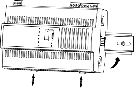
Hook the device onto the top of the DIN rail.
Push the device fully onto the DIN rail.
Release the DIN rail clips.
 AS-P-3 Server Device Installation
Connecting a Central IO Module Terminal Base to an AS-P-3 Server
AS-P-3 Server Device Installation
Connecting a Central IO Module Terminal Base to an AS-P-3 Server