
Spezifikationen
SpaceLogic RP-C-EXT-DALI-M-PD

Einleitung
SpaceLogic™ RP-C-EXT-DALI-M-PD light module connects to the SpaceLogic RP room controllers and provides I/O expansion for lighting control with DALI (Digital Addressable Lighting Interface).
Das DALI-Beleuchtungsmodul ermöglicht die Stromversorgung und die Regelung von Leuchten, die mit DALI-Vorschaltgeräten (DALI-Betriebsgeräte) ausgestattet sind.
The DALI light module is a DALI-2 certified control device (application controller) with multi-master capability. DALI-2 compliance means benefits such as improved interoperability and easier installation and maintenance. The DALI light module can be used with DALI version-1 products because DALI-2 is designed to be backward compatible with DALI version-1. The multi-master capability of the DALI light module allows the module to function as a DALI master in a DALI network and can thus work together with DALI-2 sensors and push-buttons.
Lighting can be controlled by the RP controller through motion detection and light intensity measurement provided by the Multi-sensor or Insight-Sensor, or by SpaceLogic Sensors connected to the RP controller.
The DALI light module is part of the RP controller expansion modules for connected room solution and can be combined with other modules from this product range.
Funktionen
Das DALI-Leuchtenmodul weist folgende Funktionen auf:
Stromversorgung und Kommunikation über den Raumbus
Für DALI-2 zugelassenes Steuergerät (Anwendungssteuerung)
DALI-Multi-Master-Funktion für die Kommunikation mit DALI-Sensoren und Tastern am DALI-But, was die Verdrahtungs- und Installationskosten minimiert.
Gruppen- und Einzeladressierung von DALI-Steuergeräten (Leuchten)
Ein DALI-Kanal, der in vier Ein-/Ausgänge (Anschlüsse) aufgeteilt ist, zur Stromversorgung des DALI-Bus und Regelung von bis zu 32 Leuchten und 16 Eingangsgeräte (die max. Anzahl von Leuchten und Eingangsgeräten pro Ein-/Ausgang wird durch den max. Einschaltstrom bestimmt)
Bis zu 16 DALI-Gruppen für gemeinsame Leuchtenregelung
Bis zu insgesamt 16 DALI-Eingangsgeräte. Jedes Eingangsgerät unterstützt bis zu vier Sensoren oder Taster.
Vereinfachter Inbetriebnahme-Support für an den gleichen Anschluss angeschlossene DALI-Lichter
Energiesparend durch automatisches Trennen der Stromzufuhr zu den DALI-Treibern/Vorschaltgeräten, wenn alle Lichter am gleichen Anschluss ausgeschaltet sind
Support für Ein-/Ausschaltregelung (Relais) der Nicht-DALI-Lichter an den Anschlüssen, die nicht für die DALI-Beleuchtungssteuerung verwendet werden
Vier Digitaleingänge für den Anschluss von Lichtschaltern und Fensterkontakten. Die digitalen Eingänge sind SELV (Safety Extra-Low Voltage).
Messung des Energieverbrauchs pro Modul
Geeignet für Deckenmontage
Wieland-Anschlüsse für schnelle und einfache Installation
Engage App für Raumkomfort-Einstellungen
Status-LED für das Gerät
Eine Status-LED für jeden DALI-Ein-/Ausgang
Drehschalter für die Adressenkonfiguration
Die DALI-Ein-/Ausgänge sind über das DALI-Beleuchtungsmodul an das Stromversorgungsnetz angeschlossen. Für die DALI-Busdrähte kann die Standard-Installationsausrüstung verwendet werden, die für Kleinspannungs-Installationen (ELV) zugelassen ist. Der DALI-Bus erfüllt die Anforderungen an Sicherheitskleinspannung (SELV).
The DALI-2 interface has the following features:
DALI groups can combine lights regardless of which outputs the lights belong to.
Lights that belong to the same DALI group are controlled simultaneously for switching on/off, dimming, and color temperature (tunable white) adjustment
Management of ballast and lamp alarms
Automatic addressing of lights
Durch die Verwendung einer DALI-Kanalgruppe können Sie alle DALI-Lichter, die an denselben Ein-/Ausgang (Anschluss) angeschlossen sind, als eine logische Leuchte steuern, was den Inbetriebnahmeprozess vereinfacht und beschleunigt.
The RP controller room bus allows RP controller expansion modules to be connected to the controller for people counting, motion detection, luminosity and sound pressure level measurements, Bluetooth Low Energy based applications, and control of electric lights and window blinds.
The RP-C Pro and RP-C Pro Plus controller room bus supports up to nine connected RP controller expansion modules with the following restrictions:
Maximum of two DALI light modules
Maximum of two SMI blind modules
Maximum of seven Multi-sensor or Insight-Sensor devices
The RP-C Advanced controller room bus supports up to six connected RP controller expansion modules with the following restrictions:
Maximum of two DALI light modules
Maximum of two SMI blind modules
Maximum of four Multi-sensor or Insight-Sensor devices
The RP-V Advanced controller room bus supports up to four connected RP controller expansion modules with the following restrictions:
Maximum of one DALI light module
Maximum of one SMI blind module
Maximum of two Multi-sensor or Insight-Sensor devices
Maximum total length of the room bus is 72 m (236 ft).
The Engage mobile application enables control of room temperature, fan speed, lights, and blinds/shades directly from a smartphone. A user can manage these settings when the application is connected to the RP controller.
The Engage mobile application is free and available for download from Google Play and Apple App Store.
For more information, see the Engage Specification Sheet.
|
Produkt |
Artikelnummer |
|
RP-C-EXT-DALI-M-PD
|
SXWREDAMPD10001
|
|
DIN-RAIL-CLIP, DIN-rail end clip
package of 25 pieces
|
SXWDINEND10001
|
|
Mounting plate - RP controller expansion modules
package of 5 pieces
|
SXWREMPK510001
|
Spezifikationen
| Electrical | ||||||||||||||||||||||
Nominal voltage
|
230 VAC
|
|||||||||||||||||||||
Operating voltage range
|
+/-10 %
|
|||||||||||||||||||||
Frequency
|
50/60 Hz
|
|||||||||||||||||||||
Maximum current consumption
|
10 A
|
|||||||||||||||||||||
Room bus power consumption
|
0.3 W (24 VDC)
|
|||||||||||||||||||||
Protection
|
Maximum 16 A external fuse (circuit breaker) is needed
|
|||||||||||||||||||||
Overvoltage category
|
III
|
|||||||||||||||||||||
| Environment | ||||||||||||||||||||||
Ambient temperature, operating
|
0 to 50 °C (32 to 122 °F)
|
|||||||||||||||||||||
Ambient temperature, storage
|
-20 to +70 °C (-4 to +158 °F)
|
|||||||||||||||||||||
Humidity
|
20 to 90 % RH non-condensing
|
|||||||||||||||||||||
Pollution degree
|
2
|
|||||||||||||||||||||
| Material | ||||||||||||||||||||||
Plastic flame rating
|
UL94 V-0
|
|||||||||||||||||||||
Ingress protection rating
|
IP 20
|
|||||||||||||||||||||
| Mechanical | ||||||||||||||||||||||
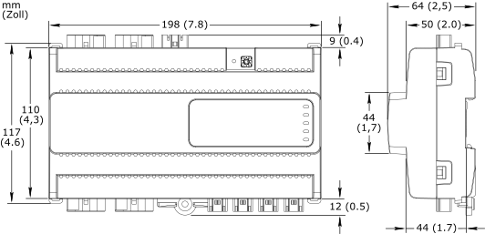
Dimensions
|
198 W x 110 H x 64 D mm (7.8 W x 4.3 H x 2.5 D in.)
|
|||||||||||||||||||||
|
||||||||||||||||||||||
Weight
|
0.433 kg (0.955 lb)
|
|||||||||||||||||||||
Recommended installation
|
DIN rail or flat surface in a cabinet
a
|
|||||||||||||||||||||
| a) It is recommended to install the device in an enclosure (cabinet), unless local regulations allow an exception. | ||||||||||||||||||||||
Connectors
|
Power input: 1 x 3-pin Wieland GST15i3 connector
|
|||||||||||||||||||||
DALI inputs/outputs: 4 x 5-pin Wieland GST15i5 connector
|
||||||||||||||||||||||
Digital inputs: 4 x 2-pin Wieland GST15i2 connector
|
||||||||||||||||||||||
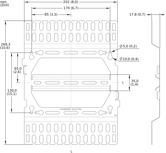
| Optional mounting plate | ||||||||||||||||||||||
| The mounting plate is used to facilitate mounting and cable management for the RP controller expansion module as well as to provide strain relief for the connectors. | ||||||||||||||||||||||
Dimensions
|
202 W x 268.3 H x 17.8 D mm (8.0 W x 10.6 H x 0.7 D in.)
|
|||||||||||||||||||||
|
||||||||||||||||||||||
Weight
|
0.306 kg (0.675 lb)
|
|||||||||||||||||||||
| Compatibility | ||||||||||||||||||||||
EcoStruxure BMS server communication
|
||||||||||||||||||||||
EcoStruxure Building Operation
|
version 3.1.1 and later
|
|||||||||||||||||||||
Energy metering support
|
||||||||||||||||||||||
EcoStruxure Building Operation
|
version 3.3.1 and later
|
|||||||||||||||||||||
DALI multi-master support
|
||||||||||||||||||||||
EcoStruxure Building Operation
|
version 4.0.1 and later
|
|||||||||||||||||||||
Support for simplified commissioning and energy saving for DALI lights, and relay control of non-DALI lights
|
||||||||||||||||||||||
EcoStruxure Building Operation
|
version 5.0.3 and later
|
|||||||||||||||||||||
| Agency compliances | ||||||||||||||||||||||
Emission
|
RCM; BS/EN 61000-6-3; BS/EN IEC 63044-5-2; FCC Part 15, Sub-part B, Class B
|
|||||||||||||||||||||
Immunity
|
BS/EN 61000-6-2; BS/EN IEC 63044-5-3
|
|||||||||||||||||||||
Safety standards
|
BS/EN 60730-1; BS/EN 60730-2-11; BS/EN IEC 63044-3
|
|||||||||||||||||||||
Digital addressable lighting interface
|
IEC 62386-101; IEC 62386-103
|
|||||||||||||||||||||
| Communication ports | ||||||||||||||||||||||
Room bus
|
RS-485
|
|||||||||||||||||||||
Dual RJ45 ports for daisy-chain configurations
|
||||||||||||||||||||||
Use a Cat 5 (or higher) cable
|
||||||||||||||||||||||
Maximum total length of the room bus: 72 m (236 ft)
|
||||||||||||||||||||||
Room bus protection
|
Transient voltage suppressors on communication and power signals
|
|||||||||||||||||||||
| Hardware | ||||||||||||||||||||||
| Main microcontroller | ||||||||||||||||||||||
CPU type
|
ARM Cortex-M4 single-core
|
|||||||||||||||||||||
Frequency
|
80 MHz
|
|||||||||||||||||||||
SRAM (embedded)
|
320 KB
|
|||||||||||||||||||||
Flash memory (embedded)
|
1024 KB
|
|||||||||||||||||||||
| Memory | ||||||||||||||||||||||
NOR flash memory
|
16 MB
|
|||||||||||||||||||||
| DALI microcontroller | ||||||||||||||||||||||
CPU type
|
ARM Cortex-M0 single-core
|
|||||||||||||||||||||
Frequency
|
32 MHz
|
|||||||||||||||||||||
SRAM (embedded)
|
8 KB
|
|||||||||||||||||||||
Flash memory (embedded)
|
64 KB
|
|||||||||||||||||||||
| Additional hardware | ||||||||||||||||||||||
Status indicator
|
LED (green and red) that shows the status of the device
|
|||||||||||||||||||||
Light status indicator
|
One status LED (green) for each DALI input/output
|
|||||||||||||||||||||
Address switch
|
Rotary switch 0 to 9
|
|||||||||||||||||||||
Set button
|
Push-button switch
|
|||||||||||||||||||||
| Energy metering | ||||||||||||||||||||||
| Messung des Energieverbrauchs | ||||||||||||||||||||||
| The energy consumption is measured in Wh, shared by the four outputs. | ||||||||||||||||||||||
Accuracy class (according to IEC 61557-12)
|
Active energy measurement: Class 1
|
|||||||||||||||||||||
Typical measurement accuracy at room temperature
|
20 to 100 W: 5%
|
|||||||||||||||||||||
100 to 3000 W: 1%
|
||||||||||||||||||||||
| DALI inputs/outputs | ||||||||||||||||||||||
Inputs/outputs
|
4, Light 1 to Light 4
|
|||||||||||||||||||||
| The four inputs/outputs share one DALI channel. | ||||||||||||||||||||||
Input/output terminals
|
N, PE, L, DA+, and DA-
|
|||||||||||||||||||||
DALI bus voltage
|
18 VDC
|
|||||||||||||||||||||
Maximum supply current
|
250 mA
|
|||||||||||||||||||||
Guaranteed supply current
|
64 mA
|
|||||||||||||||||||||
Maximum cable length
|
See the SpaceLogic Hardware Reference Guide
|
|||||||||||||||||||||
Power distribution
|
230 VAC (same voltage as power supply)
|
|||||||||||||||||||||
Maximum 5 A load per output
|
||||||||||||||||||||||
Maximum 10 A total load for the 4 outputs
|
||||||||||||||||||||||
Maximum 165 A inrush current (<20 ms) per output
|
||||||||||||||||||||||
Maximum 800 A inrush current (<200 µs) per output
|
||||||||||||||||||||||
| DALI devices | ||||||||||||||||||||||
Supported control gear
|
See table below.
|
|||||||||||||||||||||
|
||||||||||||||||||||||
| a) Color type Tc (Color temperature) of Part 209 of the IEC 62386 standard is supported. | ||||||||||||||||||||||
Supported input device types
|
See table below.
|
|||||||||||||||||||||
|
||||||||||||||||||||||
| a) Parts of the IEC 62386 standard. | ||||||||||||||||||||||
| b) For a list of supported input devices, see the Product Database on the DiiA website, www.dali-alliance.org | ||||||||||||||||||||||
| c) It is recommended to always test an input device at an early stage in a project. | ||||||||||||||||||||||
| Digital inputs | ||||||||||||||||||||||
Inputs
|
4, DI1 to DI4
|
|||||||||||||||||||||
Range
|
Dry contact, 0 to 5.0 VDC, 2.2 mA, SELV (Safety Extra-Low Voltage)
|
|||||||||||||||||||||
Anschlüsse
Follow proper installation wiring diagrams and instructions. For more information on wiring, see the SpaceLogic Hardware Reference Guide.

|
Use |
Part number |
Reference |
Connector type |
Suitable for cable diameters mm (inches) |
Marking |
Color of coding /housing |
Minimum order quantity |
|
Power supply input |
SXWRPCCONWWPOW |
91.931.4053.1 |
Female |
5.6–11 (0.22–0.43) |
L, PE, N |
Black /Black |
100 |
|
DALI inputs/outputs |
SXWRPCCONWWLIGHTPD |
91.952.4453.0 |
Male |
8.5–12.5 (0.34–0.49) |
N, PE, L, D2, D1 D2: DA+ D1: DA- |
Pastel blue /White |
50 |
|
Digital inputs |
SXWRPCCONWDI |
91.921.2353.0 |
Female |
3.4–5.5 (0.14–0.21) |
1, 2 1: DI1..4 2: RET |
Light blue /White |
100 |
The external connectors need to be ordered separately. The connectors can be ordered in quantities of 50 or 100 from Schneider Electric using the above part numbers. The connectors can also be ordered directly from Wieland using the above reference numbers. For more information, see the Wieland Electric web site.
SpaceLogic RP-C Advanced
SpaceLogic RP-C-EXT-MS-BLE
SpaceLogic RP-C-EXT-0-10V-4-PD
SpaceLogic RP-C-EXT-BL-2-LV-PD
SpaceLogic RP-C-EXT-BL-4-HV-PD
SpaceLogic RP-C-EXT-BL-SMI-2-LV-PD
SpaceLogic RP-C-EXT-BL-SMI-4-HV-PD
SpaceLogic RP-C-EXT-DALI
SpaceLogic RP-C-EXT-0-10V-4
SpaceLogic RP-C-EXT-REL-4
Commission
Engage