Concept
SMI LoVo Blind Outputs
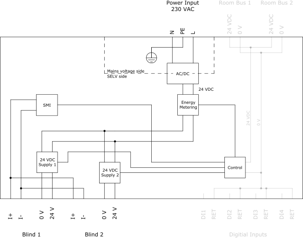
The SMI low-voltage blind modules have two Blind outputs for control of motorized window blinds (drives) that are powered by 24 VDC. The Standard Motor Interface (SMI), LoVo version for DC low-voltage drives, is used to control the blind motors.
The blind module provides one SMI channel. The blind module acts as a controller for the blind motors.
A maximum of 16 blind motors can be controlled by a blind module. The maximum number of blind motors per module and per output is also determined by the module's power distribution limitations. For more information, see section “Specifications”.
The Blind output connector has four terminals for blind motor control and power distribution:
I+
I-
0 V
24 V
The connector has a 5-pole frame, but only four poles are used in this application. For more information, see RP Series Expansion Module Pluggable Connectors .
The two power outputs are independently controlled.

The blind module uses a 24 VDC supply to connect or disconnect the 24 VDC to each blind motor (drive). In the figure above, the 24 VDC supplies are named 24 VDC Supply 1 for the Blind 1 output and 24 VDC Supply 2 for the Blind 2 output.
The 24 VDC supplies typically always connect 24 VDC to power the blind motors being controlled, but the 24 VDC supplies can be put in low power standby mode for different reasons.
The module's AC mains voltage side and low-voltage side (SELV side) are galvanically separated through the AC/DC converter.
The module's energy metering circuitry is reserved for future use (power consumption monitoring).
The SMI interface enables accurate positioning of window blinds. Accurate positioning is necessary when several blinds, awnings, or roller shutters are to be aligned. The blind module transmits the desired position through the control wires (I+ and I-) in the form of a digital command, and the electrical motor moves the blind accurately to the desired position using an internal regulator. The SMI blind motors (drives) have the end stops at the top and bottom positions pre-programmed.
The data transmission is bi-directional. The blind module transmits digital commands to the blind motor (drive), and the drive provides feedback to the module in the form of status messages. The feedback from the SMI blind motor drives is necessary when large installations are to be operated efficiently. Conventional blind motors do not support feedback.
The SMI interface supports not only commands for positioning of the blinds, but also commands for querying their current positions, and for diagnosis. The diagnostic commands can be used to detect non-operational blind motors.
For venetian blinds that use one motor drive to control both the position of the blinds and the angle of the slats, the angle is also controlled by sending a command for changing the position of the blind. The mechanics of the venetian blinds is such that the up/down movement of the blinds begins with a rotation of the slats. To achieve absolute control of the angle of the slats, measurements and calibration need to be performed during commissioning.The angle of rotation for the slats, that is, the complete rotation, needs to be measured in degrees. The result from the measurements is entered in the EcoStruxure Building Operation software to calibrate the angle of the slats. For more information, see Configuring Blinds in RP Series Expansion SMI High and Low Voltage Blind Power Modules .
Specifications
Outputs
|
2, Blind 1 to Blind 2
|
Output terminals
|
I+, I-, 0 V, and 24 V
|
Number of SMI channels
|
1
|
Maximum total number of blind motors (drives)
|
16
|
Power distribution
|
24 VDC
|
Maximum 1 A load per output
|
|
Maximum 1.3 A total load for the 2 outputs
|
|
Maximum 2 A starting current (<100 ms) per output
|
 RP Series Expansion Modules and Multi-sensors
 Blind Modules
 RP-C-EXT-BL-SMI-2-LV-PD
 RP Series Expansion Module Pluggable Connectors
 Configuring Blinds in RP Series Expansion SMI High and Low Voltage Blind Power Modules