
Spezifikationen
SpaceLogic RP-C Pro Plus

Einleitung
SpaceLogic™ RP-C Pro Plus is a high-power, fully programmable, IP based field controller that offers a multi-room connectivity hub for Connected Room Solutions.
The controller comes with pluggable connectors, with ability to distribute 24 VAC/DC power, as well as greater memory space for large room and luxury suite applications.
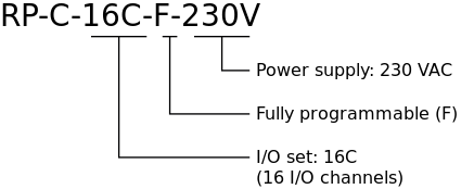
RP-C Pro Plus is a 230 VAC controller with 16 I/O points and can be mounted directly on ceilings without the need for an enclosure.
The controller is integrated into Connected Room Solutions and EcoStruxure Building Operation and is positioned for room control as well as well-being, comfort of occupants in an energy-efficient way.
The controller can either be used as a standalone BACnet/IP field controller, BACnet/SC node, or as part of an EcoStruxure BMS with a SpaceLogic AS-P or AS-B server or an Enterprise Server as the parent server.
The controller features a wireless chip, which enables commissioning of the controller with the Commission mobile application and allows tenants to change the room comfort settings using their smartphones with the Engage mobile application.
Web services enable web access directly to the controller, making the controller an open IoT hub in the room or space area.
Der RP-C Pro Plus verfügt über folgende Funktionen:
IP-fähig mit Dual-Port-Ethernet-Switch
BACnet/SC-Knoten
Controller-Modell für 230 VAC mit 16 E/A-Punkten
Vielseitiger E/A-Mix
Option, eine externe oder interne Stromversorgung für die Stromverteilung zu nutzen
Steckbare Anschlüsse zur schnellen und einfachen Installation in abgehängten Decken
Wireless-Konnektivität
Erweiterte Überwachung
Drei konfigurierbare RS-485-Ports
Sensorbus für Raumsensoren
Raumbus für vernetzte Raumlösungen
Modbus RTU-Sub-Netzwerk
KNX-Support (KNX Modbus-Gateway erforderlich)
Engage-App für Raumkomfort-Einstellungen
Commission App für die Inbetriebnahme des Controllers vor der BMS Installation
Kompletter EcoStruxure Building Operation-Software-Support mit effizienten Engineering Tools
Webservices durch RESTful API
Aktualisierung mit signierter Firmware
IP-Konnektivität, flexible Netzwerktopologien und Unterstützung für BACnet/SC-Anwendungen
The BACnet/IP controllers are based on open protocols that simplify interoperability, IP configuration, and device management, and can be enabled as BACnet/SC nodes for increased cybersecurity:
IP addressing
BACnet/IP or BACnet/SC communications
DHCP for easy network configuration
The BACnet/IP controllers have a dual-port Ethernet switch, which enables flexible network topologies:
Star
Daisy chain
Rapid Spanning Tree Protocol (RSTP) ring
In a star topology, the controller and the parent EcoStruxure BMS server are individually connected to an Ethernet switch. Daisy-chain multiple controllers together to reduce installation time and cost. When using a ring network topology, in the event of a broken IP network or a non-operational controller, RSTP will enable rapid identification of the location of the detected error while maintaining communication with the controllers on either side of the break.
BACnet/SC (Secure Connect-)Unterstützung
The BACnet/IP controllers support BACnet/SC applications as a BACnet/SC node. This allows the controllers to be used in a BACnet/SC network, which allows secure transport of BACnet traffic and information between BACnet/SC devices over private and public networks without the need for BBMDs, VLANs, and VPNs, because the BACnet/SC protocol uses WebSocket technology and TLS 1.3 encryption. In addition, BACnet/SC uses certificate management to help ensure only those devices authorized to be on a BACnet/SC network can operate on that network.
Controller-Modell für 230 VAC mit 16 E/A-Punkten
Die Reihe des RP-C Pro Plus umfasst ein RP-Controllermodell, RP-C-16C-F-230V, das einen Satz E/A-Punkttypen namens 16C umfasst und 230 VAC Spannung unterstützt.
Frei programmierbar
Der frei programmierbare RP-Controller verfügen über Skript- und Funktionsblock-Programmieroptionen und bieten so Flexibilität. Standard-Controllerapplikationen fördern die Effizienz und Standardisierung.
Vielseitige Kombinationen von E/A-Punkten
Der RP-C-16B-F-230V bietet 16 E/A-Datenpunkte, die aus vier verschiedenen Sets von E/A-Datenpunkttypen bestehen. Der vielfältige Mix von E/A-Datenpunkt-Typen passt für eine Vielzahl von Applikationen. Die universellen Eingänge/Ausgänge können flexibel als Ein- oder Ausgang konfiguriert werden.
|
I/O Point Types |
RP-C-16C-F-230V |
|
Universal I/O (Type Ub) |
4 |
|
Solid-state relay (SSR) outputs (MOSFET) |
4 a |
|
Universal I/O (Type Ub) or SSR outputs (MOSFET) b |
8 b |
- With 24 VAC/DC power distribution
- Configurable I/O point type that can be configured either as Universal I/O (Type Ub) or SSR output. When a configurable I/O point is configured as an Universal I/O (Type Ub), the SSR output is enabled and feeds 24 VAC/VDC power, but the SSR output can not be configured or used according to table “Configurations by I/O Point Types”.
|
Configurations |
Universal I/O Type Ub |
Solid-state Relay Outputs (MOSFET) |
|
Digital inputs |
yes |
- |
|
Counter inputs |
yes |
- |
|
Supervised inputs |
yes |
- |
|
Voltage inputs (0 to 10 VDC) |
yes |
- |
|
Current inputs (0 to 20 mA) |
yes |
- |
|
Temperature inputs |
yes |
- |
|
Resistive inputs |
yes |
- |
|
2-wire RTD temperature inputs |
yes |
- |
|
Voltage outputs (0 to 10 VDC) |
yes |
- |
|
Digital outputs |
- |
yes |
|
Digital pulsed outputs |
- |
yes |
|
PWM outputs |
- |
yes |
|
Tristate outputs |
- |
yes |
|
Tristate pulsed outputs |
- |
yes |
The universal inputs/outputs are ideal for any mix of temperature, pressure, flow, status points, and similar point types in a building control system.
As counter inputs, the universal inputs/outputs are commonly used in energy metering applications. As RTD inputs, they are ideal for temperature points in a building control system. As supervised inputs, they are used for security applications where it is critical to know whether or not a wire has been cut or shorted. These events provide a separate indication of alarms and events in the system.
For all analog inputs, maximum and minimum levels can be defined to automatically detect over-range and under-range values.
The universal inputs/outputs are capable of supporting analog outputs of type voltage outputs. Therefore, the universal inputs/outputs support a wide range of devices, such as actuators.
Only devices with safe extra low voltage equipment (SELV/PELV) inputs/outputs should be connected to the universal inputs/outputs.
The solid-state relay (SSR) outputs can be used in many applications to switch 24 VAC or 24 VDC on or off for external loads such as actuators, relays, or indicators. SSRs are silent and are not adversely affected by relay contact wear.
Option, eine externe oder interne Stromversorgung für die Stromverteilung zu nutzen
Der Controller bietet die Möglichkeit, zwischen einer externen Stromversorgung (24 VAC/DC, 8 A) oder dem internen Transformator (24 VAC, 19 VA) zur Stromzufuhr zu den SSR-Ausgängen zu wählen. Die Wahl wird ganz einfach durch die Platzierung einer Brücke auf einem Stiftkopf getroffen.
Steckbare Anschlüsse
Der Controller ist mit PCB-montierten Steckverbindern für den 230 VAC-Stromeingang, die E/A und den Stromeingang für eine externe Stromversorgung ausgestattet. Die PCB-montierten Steckverbinder passen zu den steckbaren Anschlüssen. Im Vergleich zum Verdrahten von Anschlussklemmen vor Ort bedeutet dies Zeitersparnis und Kostenreduzierungen für die Installation. Die Steckverbinder können vor Ort schnell und einfach verbunden werden. Die steckbaren Anschlüsse können ohne Zugentlastung und Berührungsschutz installiert werden. Da kein Gehäuse erforderlich ist, eignet sich der Controller für Nachrüstungsanwendungen und die Installation in abgehängten Decken oder Unterbodenflächen.
Wireless-Konnektivität
Der RP-Controller ist ein Bluetooth Low Energy (BLE-) fähiges Produkt. So kann der RP-C mit einem Smartphone oder einem Tablet verbunden werden und die Commission-App und Engage App zur Raumkomfort-Einstellung genutzt werden.
Through Wireless Adapter - Advanced connected to the host USB port, Zigbee TM wireless connectivity can be enabled for the RP controller. The controller can extend its point count through the Zigbee wireless network and bring flexibility in your applications. The RP controller equipped with the adapter is a Zigbee Certified Product that is compliant with Zigbee 3.0. For more information on the adapter and supported wireless devices, see the Wireless Adapter - Advanced Specification Sheet.
Erweiterte Überwachung
The BACnet/IP controllers support local trends, schedules, and alarms, enabling local operation when the controller is offline or used in standalone applications.
The battery-free power backup of the memory and real-time clock helps prevent data loss and allows seamless and quick recovery after a power disruption.
In WorkStation, you update the firmware of multiple BACnet/IP controllers at the same time and with minimum down time. The EcoStruxure BMS server keeps track of the installed firmware to support backup, restore, and replacement of the controllers and sensors. The server can host controllers of different firmware versions.
Drei konfigurierbare RS-485-Ports
Der Controller verfügt über drei konfigurierbare RS-485-Ports, die für die Unterstützung von drei verschiedenen Netzwerkarten konfiguriert werden können.
Sensor-Bus
Raum-Bus
Modbus-Netzwerk
Der Controller kann drei Netzwerke hosten, jedoch nur eines pro Netzwerktyp.
Sensorbus für Raumsensoren
The BACnet/IP controllers provide an interface designed for the SpaceLogic Sensor family of living space sensors. The SpaceLogic Sensor devices offer an efficient way to sense the temperature, humidity, CO 2 , and occupancy in a room. The SpaceLogic Sensor devices are available with different combinations of sensor types and various covers and user interface options, such as touchscreen, setpoint and override buttons, and blank covers. For more information, see the SpaceLogic Sensors - SXWS Sensors for MP and RP IP Controllers - Specification Sheet.

The RP controller sensor bus provides both power and communications for up to four sensors that are daisy-chained using standard Cat 5 (or higher) cables. This maximum number of sensors that can be connected to a controller is regardless of the sensor model and the combination of cover and sensor base type:
Blank covers: Up to four sensors of any combination of sensor base types
3-button and touchscreen covers: Up to four sensors of any combination of sensor base types
SpaceLogic LCD temperature sensors: Up to four sensors are supported
The maximum total length of the sensor bus is 61 m (200 ft). For more information, see the SpaceLogic Sensors - SXWS Sensors for MP and RP IP Controllers - Specification Sheet.
The RS-485 Power Adapter can be used for injecting 24 VDC from an external 24 VDC power supply to the bus. For more information, see the RS-485 Adapters Specification Sheet.
Raum-Bus für vernetzte Raumlösungen
The RP controller room bus allows RP controller expansion modules to be connected to the controller for people counting, motion detection, luminosity and sound pressure level measurements, Bluetooth Low Energy based applications, and control of electric lights and window blinds.
The RP-C Pro and RP-C Pro Plus controller room bus supports up to nine connected RP controller expansion modules with the following restrictions:
Maximum of two DALI light modules
Maximum of two SMI blind modules
Maximum of seven Multi-sensor or Insight-Sensor devices
Maximum total length of the room bus is 72 m (236 ft).
The RS-485 Power Adapter can be used for injecting 24 VDC from an external 24 VDC power supply to the bus. For more information, see the RS-485 Adapters Specification Sheet.
Weitere Informationen entnehmen Sie bitte den technischen Datenblättern des RP-Controllers.
Modbus RTU-Sub-Netzwerk
The RP controller Modbus network allows standard Modbus devices and the KNX Modbus gateway (RP-C-EXT-KNX) to be connected to the controller.
The Modbus RTU protocol is used for the communication. The RP controller acts as the Modbus client and the connected devices act as servers.
For connection to Modbus devices, it is recommended to use the non-isolated RS-485 adapter to provide screw termination. The adapter converts an RS-485 RJ45 interface to screw terminals. The adapter can be ordered from Schneider Electric. For more information, see the RS-485 Adapters Specification Sheet.
To connect the adapter, it is recommended that you use a Cat 5 (or higher) UTP cable with eight conductors and RJ45 connectors. The cable should be rated for the target environment and have a maximum length of 0.3 m (12 in.). The cable is not included and needs to be purchased separately.
The maximum number of Modbus devices that can be connected to an RP controller depends on the type of Modbus device and the number of Modbus registers.
The RP-C Pro Plus controller Modbus network supports up to 20 connected Modbus devices with the following restrictions:
Maximum of one KNX Modbus gateway (RP-C-EXT-KNX)
Maximum of 1,000 Modbus registers per network
64-bit Modbus registers are supported, which can be used in energy metering.
Modbus device types are pre-configured Modbus applications for quick and easy Modbus device integration in EcoStruxure Building Operation solutions. For information on the Modbus devices supported using Modbus device types, see the document EcoStruxure Building - Modbus Device Integration - Supported Device Brochure.
KNX-Unterstützung
Through the KNX Modbus gateway (RP-C-EXT-KNX), the RP controller can communicate with KNX devices such as push-buttons and sensors.
The KNX Modbus gateway provides a KNX to Modbus interface that connects to one of the RP controller's configurable RS-485 ports.
For more information, see the RP-C-EXT-KNX Specification Sheet.
Engage-App für Mobilgeräte
The Engage mobile application enables control of room temperature, fan speed, lights, and blinds/shades directly from a smartphone. A user can manage these settings when the application is connected to the RP controller.
The Engage mobile application is free and available for download from Google Play and Apple App Store.
For more information, see the Engage Specification Sheet.
Commission App
Die Commission App ermöglicht die, lokale Konfiguration, Feldanwendung und Inbetriebnahme von BACnet/IP-Controllern. Die App reduziert die Inbetriebnahmezeit, erlaubt Flexibilität bei der Durchführung des Projekts und minimiert Abhängigkeiten von der Netzwerk-Infrastruktur.
The mobile application is designed for use with Android, Apple (iOS), and Microsoft Windows 10 and Windows 11 devices. For more information, see the EcoStruxure Building Commission Specification Sheet.

Using the Commission mobile application, you can connect to one or many RP controllers. You can connect to a single RP controller using the controller's built-in Bluetooth connectivity or using the SpaceLogic Bluetooth Adapter connected to a SpaceLogic Sensor. Using a wireless access point or a network switch, you can connect to a network of RP controllers on the local IP network.
With the Commission mobile application, you can easily discover BACnet/IP controllers on the IP network. You can change the configuration of each controller, including the BACnet and IP network settings, location, and parent server. To save engineering time, you can save common device settings and then reuse them for controllers of the same model.
The Commission mobile application does not require an EcoStruxure BMS server or a network infrastructure to be in place. You can use the mobile application to load the controller application directly into the local BACnet/IP controller and deploy the controller. The controller application can be created offline using Project Configuration Tool or WorkStation. You can use the mobile application to change the behavior of an installed standard controller application, such as configuring temperature setpoints. You can also perform an I/O checkout to verify that the controller's I/O points are configured, wired, and operating correctly.
You can perform I/O checkout on the RP controller room bus to verify proper communication over the room bus between the RP controller and the associated RP controller expansion modules. Module type mismatches or address mismatches can then be resolved. After wiring the physical inputs and outputs of the RP controller expansion modules, you can perform the following tasks on the different modules:
DALI light modules: discover, wink, and associate DALI lights with the logical software points, and test individual lights
0-10V light modules: test individual lights
Blind modules: calibrate and test blinds
Relay module: test outputs
Kompletter EcoStruxure Building Operation-Software-Support
The power of the RP controller is fully realized when it is part of an EcoStruxure BMS, which provides the following benefits:
WorkStation/WebStation interface
Script and Function Block programming options
Device discovery
Engineering efficiency
Preconfigured BMS applications for HVAC and Connected Room Solutions
Zoning option
WorkStation and WebStation provide a consistent user experience regardless of which EcoStruxure BMS server the user is logged on to. The user can log on to the parent EcoStruxure BMS server to engineer, commission, supervise, and monitor the BACnet/IP controller and its I/O as well as its attached SpaceLogic Sensor devices. For more information, see the WorkStation and WebStation specification sheets.
The fully programmable RP and MP controller models have both Script and Function Block programming options. Existing programs can easily be reused between the EcoStruxure BMS server and the controller.
The enhanced Device Discovery in WorkStation enables you to easily identify BACnet/IP controllers on a BACnet network and to associate the controllers with their parent server.
The engineering and maintenance of BACnet/IP controllers can be done very efficiently using the EcoStruxure Building Operation reusability features. With these features, you can create library items (Custom Types) for a complete controller application that contains programs and all necessary objects such as trends, alarms, and schedules. The controller application in the Custom Types library is reusable across all controllers of the same model. You can use the controller application as a base for creating new controllers intended for similar applications. You can then edit the controller application, and the changes are automatically replicated to all controllers, while each controller keeps its local values.
WorkStation supports both online and offline engineering of BACnet/IP controllers. You can make the configuration changes online or use database mode to make the changes offline. In database mode, the changes are saved to the EcoStruxure Building Operation database so that you can apply the changes to the controllers later.
Project Configuration Tool enables you to perform all the engineering off site, without the need for physical hardware, which minimizes the time you need to spend on site. You can run the EcoStruxure BMS servers virtually and engineer the BACnet/IP controllers before you deploy your server and controller applications to the servers and controllers on site. For more information, see the Project Configuration Tool specification sheet.
To improve engineering efficiency and standardize engineering practices, fully designed and tested controller applications are available at bms-applications.schneider-electric.com for use with the RP controllers. This library contains applications for different RP controller models and application types, such as fan coil units, ceiling solutions, lights and blinds. These preconfigured controller applications are packages that include all software programs, and for example graphics, alarms, and documentation such as functional specifications and I/O wiring schedules, that are needed for your projects. The online repository can be accessed using common web browsers on Windows PCs as well as mobile devices running Apple iOS 11.3 (or later) and Android 6.0 Marshmallow (or later).

The Zoning option for WorkStation and WebStation provides access to an interactive zoning tool that enables easy reconfiguration of Connected Room Solutions and flexibility when switching between zones. The WebStation zoning tool provides a graphical interface that enables quick editing of zones from any web browser device.
The RP-C-16C-F-230V model supports up to eight segments, which can be used to support rezoning in a building.
Webservices
The RP controller uses the RESTful API, which allows IT web services to easily interact with software applications. The flexibility of the RESTful API allows the RP controller to handle multiple types of input and return different data formats. With Web services, clients can read/write data (BACnet values) directly from/to the controller. Web services use resource methods GET, PUT, POST, and DELETE to access and use the data. HTTPS is used for communication between the client and the controller.
The Web services function is disabled by default. When enabled, it requires approximately 200 kB of RP controller memory.
Aktualisierung mit signierter Firmware
Using digitally signed firmware provides more secure upgrading of the device. During an upgrade, the device verifies that the firmware is authentic and uncompromised Schneider Electric firmware. If the device detects discrepancies in the authenticity or integrity of the firmware, it will reject the upgrade. Once the device is upgraded with signed firmware, all upgrades thereafter must be with a signed firmware version.
|
Produkt |
Artikelnummer |
|
RP-C-16C-F-230V
|
SXWRCF16C10001
|
|
Produkt |
Artikelnummer |
|
DIN-RAIL-CLIP, DIN-rail end clip
package of 25 pieces
|
SXWDINEND10001
|
|
Mounting plate - RP-C Pro Plus
package of 5 pieces
|
SXWRCMPK510001
|
|
Non-isolated RS-485 adapter
|
SXWNISORS48510001
|
|
RS-485 power adapter
|
SXWNISORS485P10001
|
|
SpaceLogic Wireless Adapter - Advanced
|
SXWZBAUSB10001
|
|
SpaceLogic Bluetooth Adapter
|
SXWBTAECXX10001
|
|
Spare jumper
|
Samtec SNT-100-BK-G-H
|
For more information on part numbers for Network Connectivity Accessories, see the Für weitere Informationen siehe Product Selection Guide - EcoStruxure Building ..
Spezifikationen
| AC input | |||||||||||||
Nominal voltage
|
230 VAC
|
||||||||||||
Operating voltage range
|
+/-10 %
|
||||||||||||
Frequency
|
50/60 Hz
|
||||||||||||
Maximum power consumption
|
65 VA
|
||||||||||||
Power consumption without load
|
5 W
|
||||||||||||
Power input protection
|
MOV suppression and internal fuse
|
||||||||||||
Separate PTC thermistor used as a resettable fuse for the SSR outputs (DO1 to DO12) only
|
|||||||||||||
Overvoltage category
|
III
|
||||||||||||
Pollution degree
|
2
|
||||||||||||
| 24 VAC/VDC input (EXT Input) for external power supply to SSR outputs | |||||||||||||
AC voltage range
|
Maximum 30 VAC
|
||||||||||||
DC voltage range
|
Maximum 30 VDC
|
||||||||||||
EXT Input negative terminal (–), AC voltage range
|
0 to 30 VAC
|
||||||||||||
EXT Input negative terminal (–), DC voltage range
|
-30 to +30 VDC
|
||||||||||||
Maximum current consumption
|
8 A
|
||||||||||||
| Internal transformer for power supply to SSR outputs | |||||||||||||
Type
|
Isolated Class 2 output
|
||||||||||||
Nominal voltage
|
24 VAC
|
||||||||||||
Frequency
|
Same frequency as the power supply (50/60 Hz)
|
||||||||||||
Output power rating
|
19 VA
|
||||||||||||
| Environment | |||||||||||||
Ambient temperature, operating
|
0 to 50 °C (32 to 122 °F) at normal operation
|
||||||||||||
Ambient temperature, storage
|
-20 to +70 °C (-4 to +158 °F)
|
||||||||||||
Maximum humidity
|
95 % RH non-condensing
|
||||||||||||
| Material | |||||||||||||
Plastic flame rating
|
UL94 V-0
|
||||||||||||
Ingress protection rating
|
IP 20
|
||||||||||||
| Mechanical | |||||||||||||
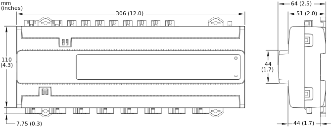
Dimensions
|
306 W x 110 H x 64 D mm (12.0 W x 4.3 H x 2.5 D in.)
|
||||||||||||
|
|||||||||||||
Weight
|
0.968 kg (2.134 lb)
|
||||||||||||
Recommended installation
|
DIN rail or flat surface
|
||||||||||||
Connectors
|
Power input: 1 x 3-pin Wieland GST15i3 connector
|
||||||||||||
External input, 24 VAC/VDC: 1 x 2-pin Wieland GST15i2 connector
|
|||||||||||||
SSR outputs: 4 x 2-pin Wieland GST15i2 connector
|
|||||||||||||
Universal I/Os: 4 x 2-pin Wieland GST15i2 connector
|
|||||||||||||
SSR outputs or Universal IOs: 8 x 4-pin Wieland GST15i4 connector
|
|||||||||||||
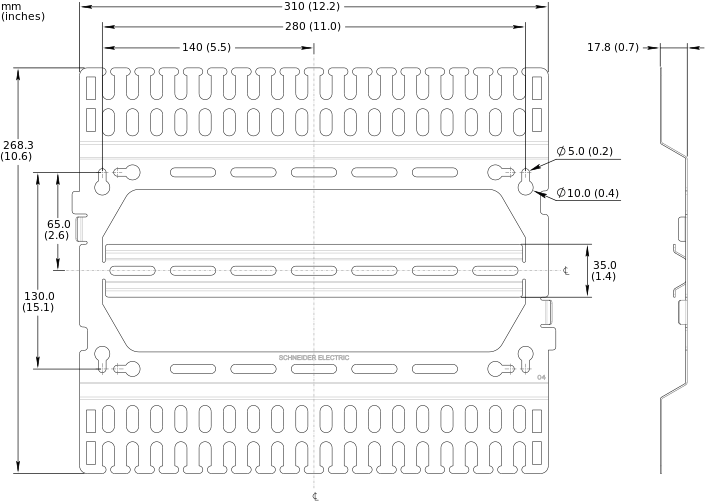
| Optional mounting plate | |||||||||||||
| The mounting plate is used to facilitate mounting and cable management for the RP-C Pro Plus controller as well as to provide strain relief for the connectors. | |||||||||||||
Dimensions
|
310 W x 268.3 H x 17.8 D mm (12.2 W x 10.6 H x 0.7 D in.)
|
||||||||||||
|
|||||||||||||
Weight
|
0.458 kg (1.01 lb)
|
||||||||||||
| Compatibility | |||||||||||||
EcoStruxure BMS server communication
|
|||||||||||||
EcoStruxure Building Operation
|
version 5.0.1 and later
|
||||||||||||
BACnet/SC network support
|
|||||||||||||
EcoStruxure Building Operation
|
version 6.0.1 and later
|
||||||||||||
| Agency compliances | |||||||||||||
Emission
|
RCM; BS/EN 61000-6-3; BS/EN IEC 63044-5-2
|
||||||||||||
Immunity
|
BS/EN 61000-6-2; BS/EN IEC 63044-5-3
|
||||||||||||
Radio
|
ETSI EN 300 328 V2.2.2
|
||||||||||||
Safety standards
|
BS/EN 60730-1; BS/EN 60730-2-11; BS/EN IEC 63044-3
|
||||||||||||
| Real-time clock | |||||||||||||
Accuracy, at 25 °C (77 °F)
|
+/-1 minute per month
|
||||||||||||
Backup time, at 25 °C (77 °F)
|
7 days minimum
|
||||||||||||
| Communication ports | |||||||||||||
Ethernet
|
Dual 10/100BASE-TX (RJ45), IEEE 802.3 compliant
|
||||||||||||
USB
|
1 USB 2.0 host port (type-A), 5 VDC, 2.5 W
|
||||||||||||
RS-485 port Com A
|
24 VDC, 3 W, RS-485 (RJ45)
|
||||||||||||
Transient voltage suppressors on communication and power signals
|
|||||||||||||
RS-485 port Com B
|
24 VDC, 3 W, RS-485 (RJ45)
|
||||||||||||
Transient voltage suppressors on communication and power signals
|
|||||||||||||
RS-485 port Com C
|
24 VDC, 3 W, RS-485 (RJ45)
|
||||||||||||
Transient voltage suppressors on communication and power signals
|
|||||||||||||
| RS-485 transceiver characteristics | |||||||||||||
Transceiver type
|
Failsafe
|
||||||||||||
Non-isolated
|
|||||||||||||
External biasing
|
None required
|
||||||||||||
Total Unit Load (UL) per device
|
Maximum 0.5 UL
|
||||||||||||
| Communications | |||||||||||||
BACnet
|
BACnet/IP, port configurable, default 47808
|
||||||||||||
BACnet/SC, port configurable, no default port
|
|||||||||||||
BTL B-AAC (BACnet Advanced Application Controller), B-GW (BACnet Gateway)
a
|
|||||||||||||
| a) See the BTL Product Catalog for up-to-date details on BTL listed firmware revisions on BACnet International's home page. | |||||||||||||
| Wireless connectivity | |||||||||||||
| Bluetooth Low Energy | |||||||||||||
Communication protocol
|
Bluetooth
®
5.1 Low Energy compliant
|
||||||||||||
Frequency
|
2.402 to 2.480 GHz
|
||||||||||||
Maximum output power
|
10 dBm
|
||||||||||||
Maximum communication distance
|
Line-of-sight: 100 m (328 ft)
|
||||||||||||
Antenna
|
Integrated antenna
|
||||||||||||
RF connector for optional external antenna
|
SMA connector
|
||||||||||||
External antenna (optional)
|
Restricted to the approved antenna type listed below (used in certification)
|
||||||||||||
|
|||||||||||||
| CPU | |||||||||||||
Frequency
|
500 MHz
|
||||||||||||
Type
|
ARM Cortex-A7 dual-core
|
||||||||||||
DDR3 SDRAM
|
128 MB
|
||||||||||||
NOR flash memory
|
64 MB
|
||||||||||||
Memory backup
|
128 kB, FRAM, non-volatile
|
||||||||||||
| Universal inputs/outputs | |||||||||||||
Channels
|
4, Ub9 to Ub12
|
||||||||||||
Absolute maximum ratings
|
-0.5 to +24 VDC
|
||||||||||||
A/D converter resolution
|
16 bits
|
||||||||||||
Universal input/output protection
|
Transient voltage suppressor on each universal input/output
|
||||||||||||
| Digital inputs | |||||||||||||
Range
|
Dry contact switch closure or open collector/open drain, 24 VDC, typical wetting current 2.4 mA
|
||||||||||||
Minimum pulse width
|
150 ms
|
||||||||||||
| Counter inputs | |||||||||||||
Range
|
Dry contact switch closure or open collector/open drain, 24 VDC, typical wetting current 2.4 mA
|
||||||||||||
Minimum pulse width
|
20 ms
|
||||||||||||
Maximum frequency
|
25 Hz
|
||||||||||||
| Supervised inputs | |||||||||||||
5 V circuit, 1 or 2 resistors
|
|||||||||||||
Monitored switch combinations
|
Series only, parallel only, and series and parallel
|
||||||||||||
Resistor range
|
1 to 10 kohm
|
||||||||||||
| For a 2-resistor configuration, each resistor must have the same value +/- 5 % | |||||||||||||
| Voltage inputs | |||||||||||||
Range
|
0 to 10 VDC
|
||||||||||||
Accuracy
|
+/-(7 mV + 0.2 % of reading)
|
||||||||||||
Resolution
|
1.0 mV
|
||||||||||||
Impedance
|
1 Mohm
|
||||||||||||
| Current inputs | |||||||||||||
Range
|
0 to 20 mA
|
||||||||||||
Accuracy
|
+/-(0.01 mA + 0.4 % of reading)
|
||||||||||||
Resolution
|
1 μA
|
||||||||||||
Impedance
|
47 ohm
|
||||||||||||
| Resistive inputs | |||||||||||||
10 ohm to 10 kohm accuracy
|
+/-(7 + 4 x 10
-3
x R) ohm
|
||||||||||||
| R = Resistance in ohm | |||||||||||||
10 kohm to 60 kohm accuracy
|
+/-(4 x 10
-3
x R + 7 x 10
-8
x R
2
) ohm
|
||||||||||||
| R = Resistance in ohm | |||||||||||||
| Temperature inputs (thermistors) | |||||||||||||
Range
|
-50 to +150 °C (-58 to +302 °F)
|
||||||||||||
| Supported thermistors | |||||||||||||
Honeywell
|
20 kohm
|
||||||||||||
Type I (Continuum)
|
10 kohm
|
||||||||||||
Type II (I/NET)
|
10 kohm
|
||||||||||||
Type III (Satchwell)
|
10 kohm
|
||||||||||||
Type IV (FD)
|
10 kohm
|
||||||||||||
Type V (FD w/ 11k shunt)
|
Linearized 10 kohm
|
||||||||||||
Satchwell D?T
|
Linearized 10 kohm
|
||||||||||||
Johnson Controls
|
2.2 kohm
|
||||||||||||
Xenta
|
1.8 kohm
|
||||||||||||
Balco
|
1 kohm
|
||||||||||||
| Measurement accuracy | |||||||||||||
20 kohm
|
-50 to -30 °C: +/-1.5 °C (-58 to -22 °F: +/-2.7 °F)
|
||||||||||||
-30 to 0 °C: +/-0.5 °C (-22 to +32 °F: +/-0.9 °F)
|
|||||||||||||
0 to 100 °C: +/-0.2 °C (32 to 212 °F: +/-0.4 °F)
|
|||||||||||||
100 to 150 °C: +/-0.5 °C (212 to 302 °F: +/-0.9 °F)
|
|||||||||||||
10 kohm, 2.2 kohm, and 1.8 kohm
|
-50 to -30 °C: +/-0.75 °C (-58 to -22 °F: +/-1.35 °F)
|
||||||||||||
-30 to +100 °C: +/-0.2 °C (-22 to +212 °F: +/-0.4 °F)
|
|||||||||||||
100 to 150 °C: +/-0.5 °C (212 to 302 °F: +/-0.9 °F)
|
|||||||||||||
Linearized 10 kohm
|
-50 to -30 °C: +/-2.0 °C (-58 to -22 °F: +/-3.6 °F)
|
||||||||||||
-30 to 0 °C: +/-0.75 °C (-22 to +32 °F: +/-1.35 °F)
|
|||||||||||||
0 to 100 °C: +/-0.2 °C (32 to 212 °F: +/-0.4 °F)
|
|||||||||||||
100 to 150 °C: +/-0.5 °C (212 to 302 °F: +/-0.9 °F)
|
|||||||||||||
1 kohm
|
-50 to +150 °C: +/-1.0 °C (-58 to +302° F: +/-1.8 °F)
|
||||||||||||
| RTD temperature inputs | |||||||||||||
Supported RTDs
|
Pt1000, Ni1000, and LG-Ni1000
|
||||||||||||
| Pt1000 | |||||||||||||
Sensor range
|
-50 to +150 °C (-58 to +302 °F)
|
||||||||||||
|
|||||||||||||
| Ni1000 | |||||||||||||
Sensor range
|
-50 to +150 °C (-58 to +302 °F)
|
||||||||||||
|
|||||||||||||
| LG-Ni1000 | |||||||||||||
Sensor range
|
-50 to +150 °C (-58 to +302 °F)
|
||||||||||||
|
|||||||||||||
| RTD temperature wiring | |||||||||||||
Maximum wire resistance
|
20 ohm/wire (40 ohm total)
|
||||||||||||
Maximum wire capacitance
|
60 nF
|
||||||||||||
| The wire resistance and capacitance typically corresponds to a 200 m wire. | |||||||||||||
| Voltage outputs | |||||||||||||
Range
|
0 to 10 VDC
|
||||||||||||
Accuracy
|
+/-60 mV
|
||||||||||||
Resolution
|
10 mV
|
||||||||||||
Minimum load resistance
|
2.4 kohm
|
||||||||||||
Source current
|
+4.2 mA
|
||||||||||||
Sink current
|
-1 mA (0 to 0.4 VDC)
|
||||||||||||
-4.2 mA (0.4 to 10 VDC)
|
|||||||||||||
| Solid-state relay outputs, DO | |||||||||||||
Channels
|
4, DO9 to DO12
|
||||||||||||
Output rating
|
Maximum 2 A load for the “C” group of 2 outputs
|
||||||||||||
Maximum 2 A load for the “D” group of 2 outputs
|
|||||||||||||
Minimum pulse width
|
100 ms
|
||||||||||||
Solid-state relay output protection
|
Transient voltage suppressor across each solid-state relay (SSR) output
|
||||||||||||
| Configurable solid-state relay outputs or universal inputs/outputs | |||||||||||||
Channels
|
8 configurable SSR outputs (DO) or universal inputs/outputs (Ub)
|
||||||||||||
| Universal inputs/outputs | |||||||||||||
| The specifications for the configurable universal inputs/outputs Ub1 to Ub8 are the same as for Ub9 to Ub12, with the exception for the number of channels. For information on the common specifications, see section “Universal inputs/outputs” above. | |||||||||||||
Channels
|
8, Ub1 to Ub8
|
||||||||||||
| Solid-state relay outputs | |||||||||||||
| The specifications for the configurable solid-state relay outputs DO1 to DO8 are the same as for DO9 to DO12, with the exception for the number of channels and the output rating. For information on the common specifications, see section “Solid-state relay outputs, DO” above. | |||||||||||||
Channels
|
8, DO1 to DO8
|
||||||||||||
Output rating
|
Maximum 2 A load for the “A” group of 4 outputs
|
||||||||||||
Maximum 2 A load for the “B” group of 4 outputs
|
|||||||||||||
Verbindungen
For more information on wiring, see the SpaceLogic Hardware Reference Guide.

|
Use |
Part number |
Reference |
Connector type |
Suitable for cable diameters mm (inches) |
Marking |
Color of coding /housing |
Minimum order quantity |
|
Power supply input |
SXWRPCCONWWPOW |
91.931.4053.1 |
Female, 3-pole |
5.6–11 (0.22–0.43) |
L, PE, N |
Black /Black |
100 |
|
External input, 24 VAC / VDC |
SXWRPCCONPOWIP |
91.921.3053.0 |
Female, 2-pole |
6–7.7 (0.24–0.30) |
L, N |
White /White |
100 |
|
SSR outputs (DO), 24 VAC / VDC |
SXWRPCCONDCOP |
91.922.3053.0 |
Male, 2-pole |
6–7.7 (0.24–0.30) |
L, N |
White /White |
100 |
|
Universal I/O (Ub) |
SXWRPCCONWWLIGHT2 |
91.922.3353.0 |
Male, 2-pole |
6–7.7 (0.24–0.30) |
2, 1 |
Light blue /White |
100 |
|
Configurable SSR outputs (DO) or Universal I/O (Ub) |
SXWRPCCONUIO |
91.942.4650.0 |
Male, 4-pole |
6.5–12 (0.26–0.47) |
1, 2, 3, 4/N |
Turquoise blue /White |
100 |
The external connectors need to be ordered separately. The connectors can be ordered in quantities of 100 from Schneider Electric using the above part numbers. The connectors can also be ordered directly from Wieland using the above reference numbers. For more information, see the Wieland Electric web site.
Enterprise Server
SpaceLogic AS-P
SpaceLogic AS-B
WorkStation
WebStation
SpaceLogic RP-C-EXT-MS-BLE
Insight-Sensor: RP-C-EXT-IS-BLE
SpaceLogic RP-C-EXT-DALI-M-PD
SpaceLogic RP-C-EXT-DALI
SpaceLogic RP-C-EXT-0-10V-4-PD
SpaceLogic RP-C-EXT-0-10V-4
SpaceLogic RP-C-EXT-BL-4-HV-PD
SpaceLogic RP-C-EXT-BL-2-LV-PD
SpaceLogic RP-C-EXT-BL-SMI-4-HV-PD
SpaceLogic RP-C-EXT-BL-SMI-2-LV-PD
SpaceLogic RP-C-EXT-REL-4
SpaceLogic CRS-HH-REL-10
Spacelogic RP-C-EXT-KNX
SpaceLogic drahtloser Adapter – Advanced
RP-C-RC-BLE
Commission
Engage
Project Configuration Tool – Version 2
Automated Engineering Tool